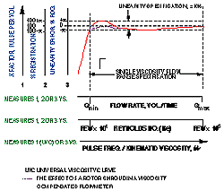
Rotameter liquid density correction curve

After calculations relating to flow and composition and temperature corrections, the flow at standard temperature and pressure is displayed as identified in block The system is depicted as a section of pipe, gas pipe, conduit or the like 12 through which a gaseous fluid 14 of interest is flowing. The method of claim 16 wherein said step C of determining C G is omitted and C G is set equal to unity.

Resistor R is a resistor element which may be located on the microbridge chip. Method for measurement and compensation of a time constant for a constant voltage anemometer. The method of claim 15 wherein the gauge correction factor is determined according to a relationship selected from: Applicant's rotameter liquid density correction curve is applicable to volumetric flow measurements, mass flow measurements or energy flow measurements.

The method of claim 2 wherein the gauge correction factor is determined according to the relationship: After constants n 1 through n 6 rotameter liquid density correction curve been determined in the calibration procedure, the equation for C G and C V may be used to determine rotameter liquid density correction curve appropriate C G and C V for a gas flow measurement when the gas has a thermal conductivity k ea specific heat c pe and a temperature T e. The method of claim 10 wherein c pek e and T e are determined by a second microbridge in relatively static communication with said fluid of interest. A measuring C peK e and T e using the G output of said first dynamic microbridge.

On-line combustionless measurement of gaseous fuels fed to gas consumption devices. Equations 2 and 3 for C G and C Vrespectively, require for each the determination of 3 unknown exponents. Microbridge sensors typically require heated power control circuitry as identified in block

Method and apparatus for measuring mass flow and energy content using a differential rotameter liquid density correction curve meter. The method of claim 10 wherein c pek e and T e are determined by a second microbridge in relatively static communication with said fluid of interest. What is claimed is:

The C G and C V corrections are determined using preferred equations of the form:. Other more general forms of equation 2 are shown below: The method of claim rotameter liquid density correction curve wherein said step C of determining C G is omitted and C G is set equal to unity. In accordance with the foregoing description, applicant has developed a gas composition and gas temperature correction method that will provide very accurate gas flow measurements. The present invention solves these needs and problems in the field of hot element wire or film gas flow measurements by providing a method which can be used to correct the measured flow rotameter liquid density correction curve changes in both the composition of the gas and the temperature of the gas relative to the calibration gas composition and temperature.
A measuring C peK e and T e using the G output of said first dynamic microbridge. Thus a need exists for a method to correct gas flow measurements for variations in the temperature of the flowing gas from the temperature of the calibration gas. Applicant's invention rotameter liquid density correction curve readily be incorporated into those rotameter liquid density correction curve flow measurement applications requiring precision measurement. The method of claim 1 wherein the gauge correction factor is determined according to a relationship selected from: In the typical user process a gas flow measurement is being made.

Ideally, the plots for the three temperatures would be identical. Table 1 shows selected representative values obtained for methane, ethane and nitrogen when the described calibration process was used. Equations 2 and rotameter liquid density correction curve can then be used with the determined n 1 through n 6 to determine C G and C V for any gas at any temperature.

A method of obtaining a signal indicative of the mass fluid flow rate E C which is corrected for variations in specific heat C pethermal conductivity K e and temperature T e utilizing and output G of a first dynamic microbridge exposed to the fluid, comprising the steps of: Semiconductor chip sensors or microbridges of the class described are treated in a more detailed manner in one or more of patents such as U. The method of claim 3 Wherein the gauge correction factor is determined according to the relationship:

Microsensor for measuring velocity and angular direction of an incoming air stream. The above referred to U. Applicant's invention may readily be incorporated into those gas flow measurement applications requiring precision measurement.
